Just as I was looking for a new project to do, my wife asked me what I thought about trying a sunrise alarm clock. I looked at them and talked with her a little bit and decided I could build us something quickly that would suit the basic needs, let us test the idea, and cost less (before you count my time).
Where to get it:
-
Source Code:
-
PCB or Gerber files:
For personal use only - see template license.
OshPark - Current Revision(old revisions)
-
Other Parts
DigiKey Cart
I've put together an example BOM from DigiKey for the remaining parts.
There are a few substitutions:- Stackable header -> Female Header (to cleanup the extra pins on top)
- Jameco LED -> DigiKey LED (to simplify ordering)
- Resistors -> DigiKey Resistors (I used what I had handy, but these are the correct values and similar power rating)
I hope you find this useful.
Rev 1: Tuning the software:
I started with these things in mind:
- It should automatically find the time via wifi or other method
- It should gradually fade in over 30 minutes (from full off to full on)
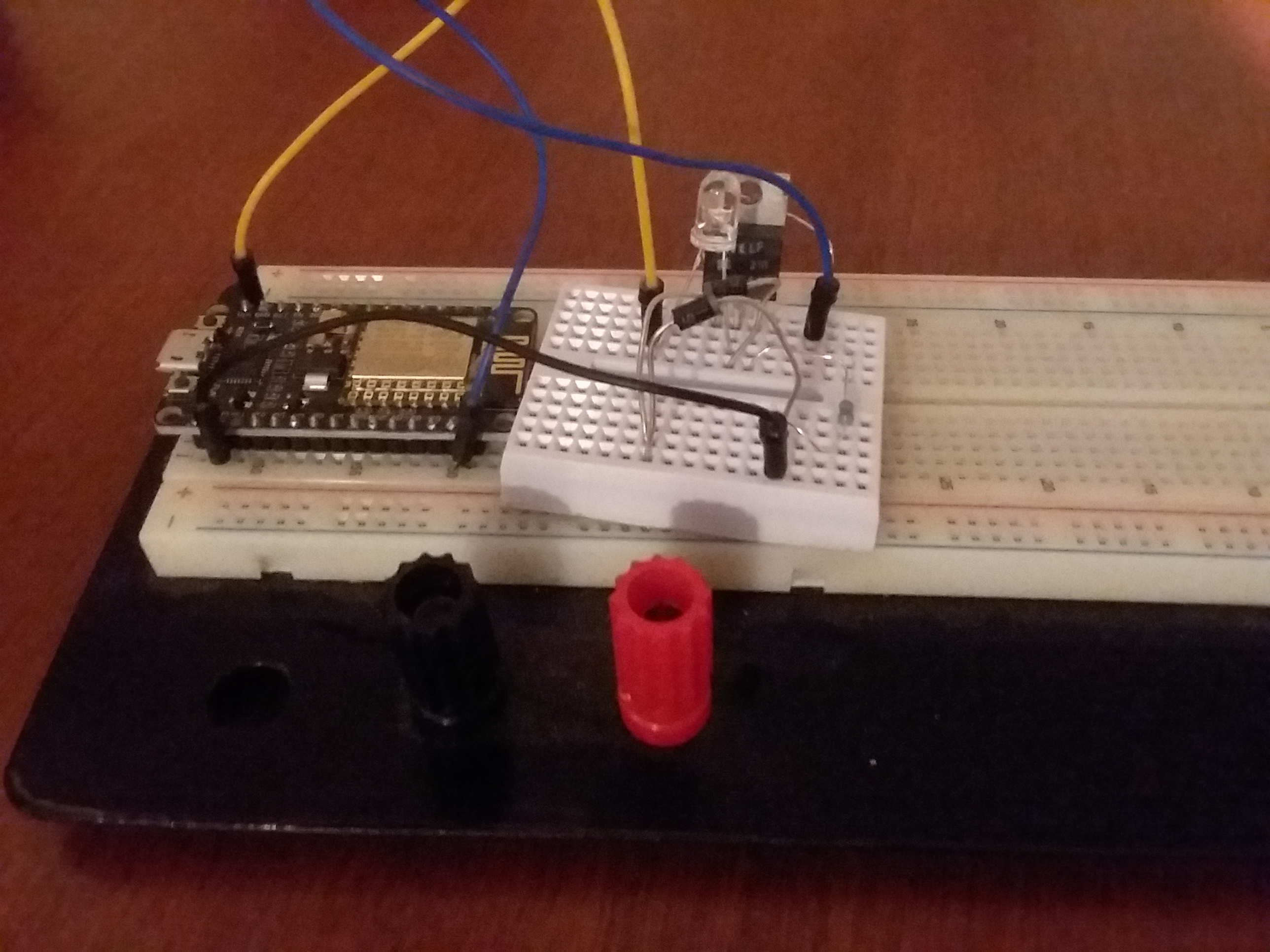
I had at my disposal a NodeMCU development board which uses the ESP8266 wifi chip and is Arduino IDE compatible, so I set to work creating an HTTP server to handle our needs.
(I’m not going to go into a whole lot of detail on this software rev as I have completely abandoned it, but I will post the code here for the curious).
Next was the light. After some searching on my usual sources, I selected the LED White T1-3/4 at Jameco Electronics
I knew that running this LED at full brightness was going to require a bit of current draw, and I didn’t want to fry my dev board, so I did some looking to see if I could find an example LED driver that used a transistor for the main current gate (my own previous attempts to design this from scratch had not worked, and had fried the dev boards). I wanted to use an NPN transistor (like the 2n2222a) to make sure it would be easy to work with (or at least in my mind).
The basic layout is to have a control signal from the dev board turn the transistor on and allow current to flow
from the LED to ground.
Because and LED is almost a short, you have to put a small resistor in series to make sure there is a little bit
of a current limiter.
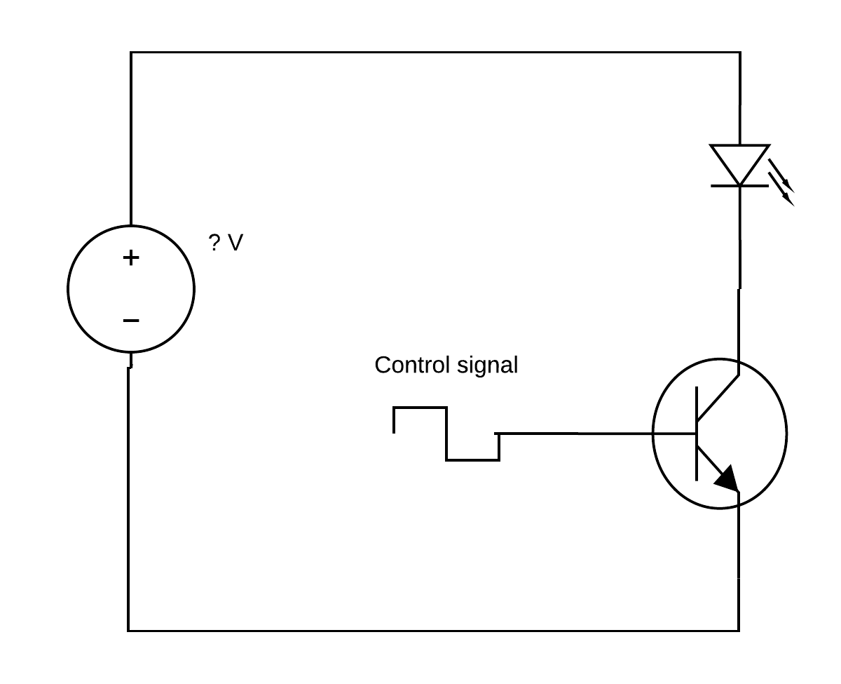
The problem here is that the control signal will flow through the transistor to the resistor to ground as well.
And the effect is the voltage at the gate and at the sync match the control signal and the transistor does not
turn on
(it needs at least like .7V to turn on, although that varies by transistor).
On top of that, at 5V, the control signal is outputting 5V / 100 ohms = .05 Amps
– which is on the border of what you should pull from an Arduino.
I knew I could reduce the current by putting a second resistor in series with the control signal.
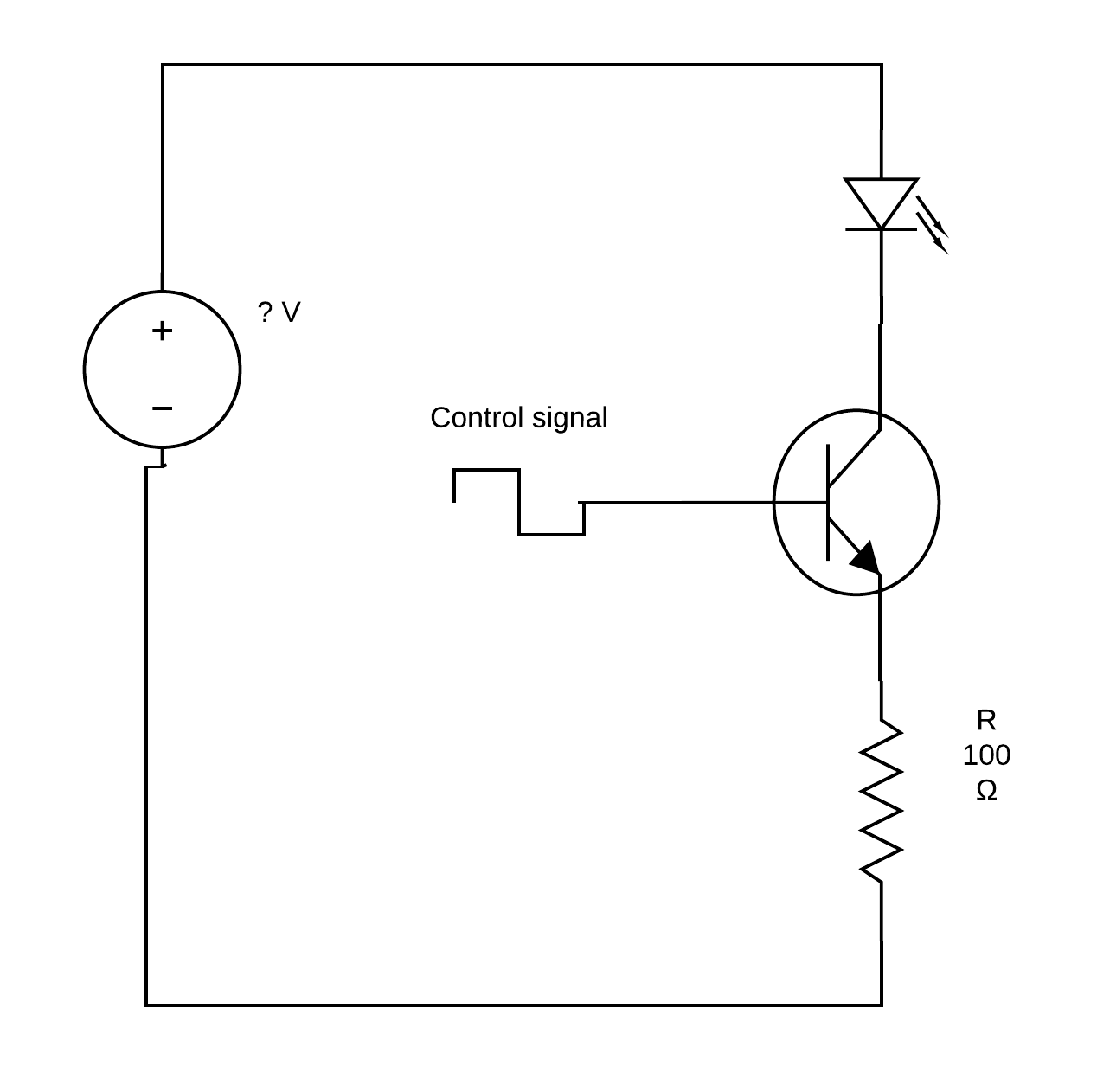
However, this does not solve the problem with not being able to turn on the transistor.
After some Google-ing, I found a post by John_Smith that uses two diodes in series to solve the voltage level problem (I remembered from school that the drop across a diode tends to be about .7V, so putting two in would lock the input to the transistor at roughtly 1.4V and pull it to ground once the control went low). This solved my issue.
This solved my control issues. You’ll notice that I didn’t specify the voltage level or the transistor I used, I opted to get the LED that I did because it handle a decent current – 30 mA – going through it. That would allow me to set the input voltage at anything I wanted up to 30V to get the desired brightness (although I do not expect much of a visible difference beyond about 5 or 6 V).
With this bread-boarded, it was time to code a server.
Here, I relied heavily on the ESP8266 group's documentation for getting my Arduino IDE setup and going.
Couple of things I did in the code:
- I depended on a local server I had to host a page that printed the current time stamp which I had the alarm grab on boot to figure out what time it was.
- I also had that server providing the html, css, and javascript to make a nice UI, and forwarding all the requests for current and changes to the configuration in the form of GET requests to the NodeMCU. This minimized the amount of data I was storing on the NodeMCU for the web page.
- I had the program check what brightness it should set the light at based on the current time and the time of the current alarm (if alarms were on), then check if there were any HTTP requests (handle them if so) but continue if not. This allowed for the web server to not interfere with setting the brightness, but I could also pull up the web page on my phone and tweak it whenever I wanted.
This worked pretty well for us, but we eventually decided that week-day and week-end with the whole thing being on or off wasn’t enough control (in particular, we wanted to have it off on Saturdays without having to remember to turn it back on for Sunday).
Rev 2 Cleaning up the Hardware:
After we had been using this alarm for a couple of weeks,
we were pretty sure we liked it and that I should proceed to making it a little more permanent.
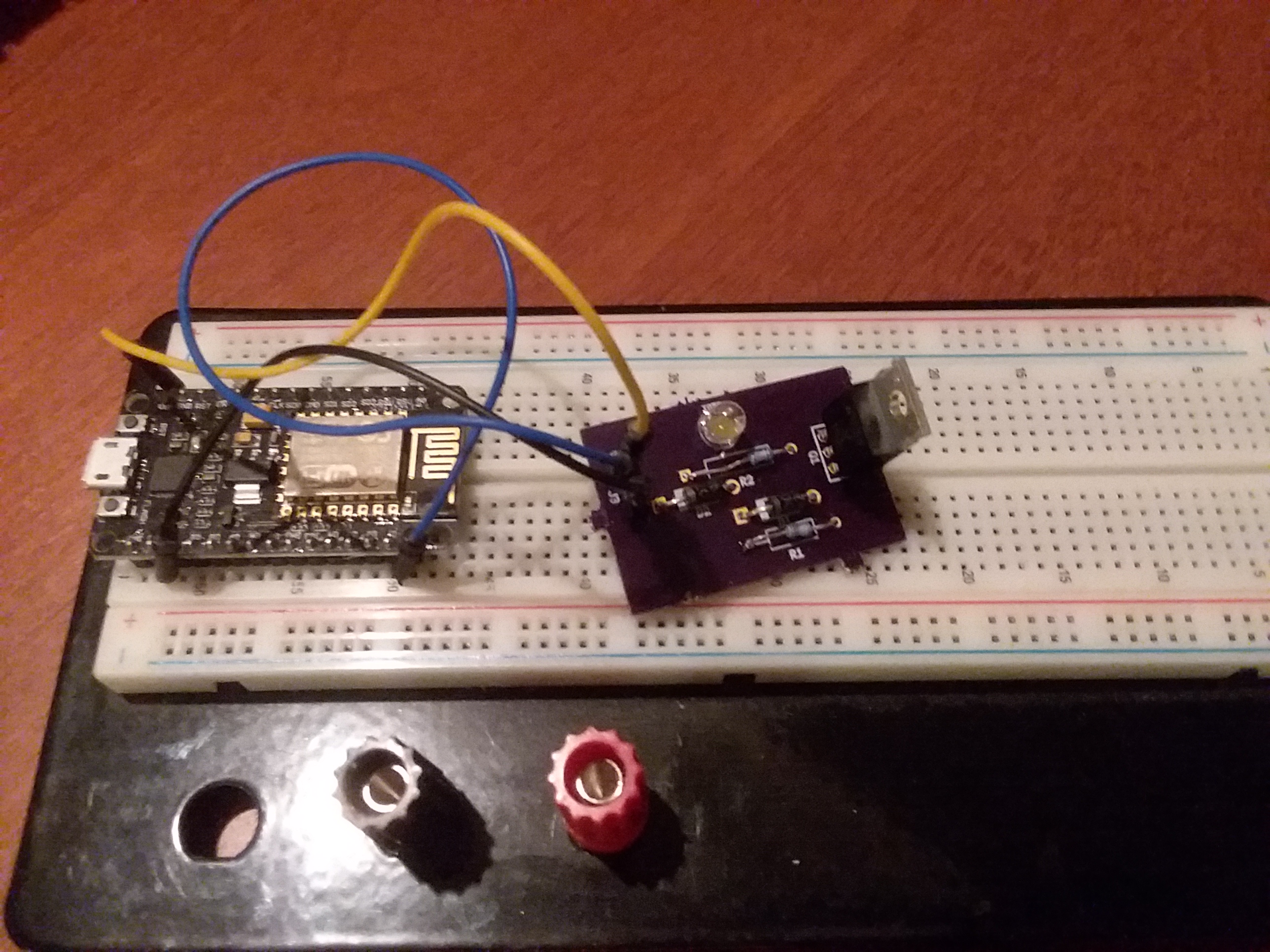
So, I took the schematic for the driver and used MultiSim/Ultiboard desktop (which I have access to through my
day job) and designed a PCB.
I ordered off to Oshpark and had a
couple made.
I soldered one up, and that was the install that went into place in our new apartment (there was a move in there
that caused a delay in getting things done).
Around this time, we started having issues with my Wi-Fi router
(hey, I bought it from Goodwill and it was two years old, so . . . yeah this was coming at some point).
When we got that all sorted (the first replacement we got didn’t work),
I had a lot of trouble getting the NodeMCU to connect to the new router.
I did find that after letting it sit for about a week, it connected right up, but that’s not really a workable
solution
(I’m not sure what the problem is, if it’s related to IP reservations which I have set to a 24hr period, or
what).
On top of that, I had never been able to get the hostname to set correctly and the new router didn’t want to
assign it the reserved IP I wanted it to,
so I was having to update my server relay code every time I fought the connectivity again.
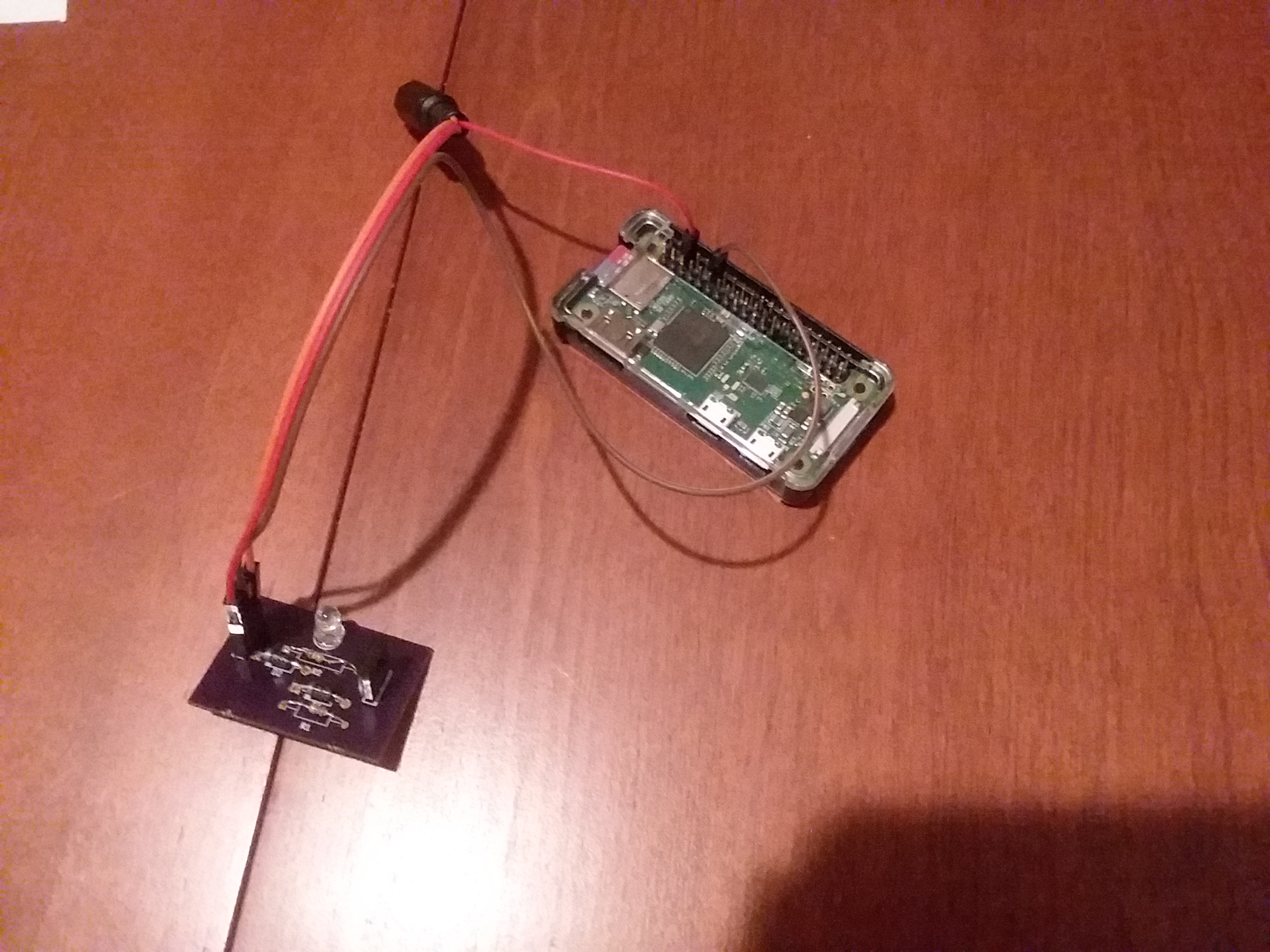
Eventually I had had enough and decided to order a Raspberry Pi 0 to run my circuit board.
Rev 3 Lowering the driver current:
Now, the original circuit design would pull about 30 mA, which is too high for the RasPi-0 gpio pins ; so, it was time to rev the hardware again.
I decided to increase the input resistor to 1k and see what that did. That dropped the expected current down to 3mA, which is sufficiently low.
Conveniently, this meant I could re-use the same boards I had made earlier and just swap one of the resistors for a higher value.
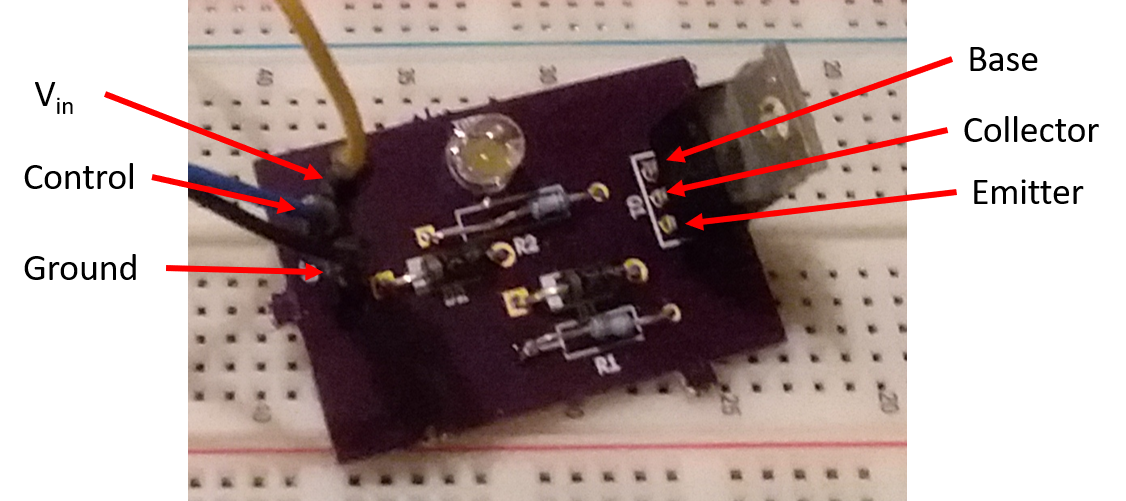
I realized after the fact that I should have used the silk screen to label the Vin, Control, Ground pins as well as the Collector, Emmitter, and Base pins on the transistor.
Rev 4 Translating code to Python: - November 2018
You may have realized earlier that the NodeMCU runs Arduino C, and the RasPi runs Python (or at least that’s the most pushed programming language for it. Since it’s a Linux machine, it can run compiled C code). I set to work translating the concept of the web server and configuration to Python.
Couple of things I wanted to take advantage of:
- The system time – rather then depending on another server for the time
- TinyDB – to store and reload the configuration easily
- The RasPI-0’s speed and run the whole web server and LED control in one place
- Unit testing! – this was something that was sorely lacking in the Arduino environment (I’m not saying it’s impossible, just non-intuitive), if you look at the source for the this version of the project, you’ll see that I have a decent number of unit tests around the concept of an alarm, what days it should be active, and even around the alarm composite I wrote and the database being able to store and reload the config.
One last thing I had to take care of, piping 5V through the RasPi was not working, so I soldered a barrel jack to provide Vin to my LED Driver, with a ground tied to the RasPi.
Due to the fact that we decided we liked this, I opted to shorten my time to market by delivering the absolute
bare minimum needed to make it work.
There is no web interface on this version (although I did create an HTTP server to set it up), and the command
line interface (CLI) is extremely limited.
To use it, one must:
- install the dependencies,
- run the CLI
- add the desired number of alarms
- quit the application
- open the alarms.json file in a text editor
- set the desired times and days (referencing how the flags work) for each alarm,
- restart the CLI and let it run.
Rev 5 Fixing a few issues: - December 2018
When I initially soldered the barrel jack, I apparently had a bad connection, this was troublesome.
Also, the LED appeared to flash a little (when it did work despite the barell jack). In particular, it would get overly bright then resume the correct brightness on most steps (which are set to once per second).
After some searching the forums, I came across this thread that stated that one needs to use pigpio (or similar) and gives an example.
Turns out that gpiozero is a software timed PWM (which is fine for servos and the like that can't physically respond to one pulse being different than the rest, but is visible on an LED).
I used the example to test if this did resolve the issue, and (becuase it does) I have now upgraded the software (and corresponding tests) to use pigpio instead.
Also moved all the unit tests under the UnitTest folder and made a master run file.
Rev 6: Hardware Rev - June 2019
After my last post, Nechoha replied pointing out that I could use a different setup to limit the current from the controller by moving the resistor before the
I replied to them and said I would be making a rev in January to turn the circuit into a shield and would include this update at that point. Well, January came late this year.
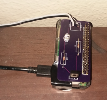
I've made a new rev using this simplified circuit and turning it into a RasPI shield (I'm saying shield instead of HAT because I did not include in ID EEPROM).
I published the shield template I had to make on GitHub, ordered my board from OshPark again (Sunrise Alarm RasPi0 Shield), and ordered a header from DigiKey.
I also learned from my last rev and included silk screen labeling on the Transistor arrangement and the resistor values (and power direction).
I've signed up to present this at a Maker fair coming up at the start of August, so I should have this assembled ahead of time and be able to post back by then, but given how long it took to get to this one, . . .
Rev 7: Fixing Hardware and Software - July 2019
I said I would post back once I got the PCB in and had actually attempted to assemble. Here goes.
PCB Isuses:
- Hole size for connector was too small
Fixed by using a security camera power tail (femail barell jack) instead (cable was small enough to fit an solder into holes). -
Anular rings on resistors too small
Just dealt with it on the Rev6 board, but increased the pad size on the new version. -
Silk screen orientated incorrectly for LED
Just dealt with it on the Rev6 board, but adjusted component on the new version.
Software Isuses:
- The light would make dramatic steps each minute and not adjust any more granularly
Turns out the code to determine time to full bright (because it adjusts a time.now() to the target hour and minute) was constantly shifting the target second. Added a unit test to prove this and resolved by fixing the target seconds to 0.
Those issues asside, it does work pretty well.
Some Future Improvements:
- Fixing the setup.py so it works correctly to install the minimum version of dependencies
- Actually adding a web interface.
- Setting up for the script to run as a service in the background
- Automating the setup to one script